

Contacts
-

Lead Instrument Scientist
-

Instrument Scientist
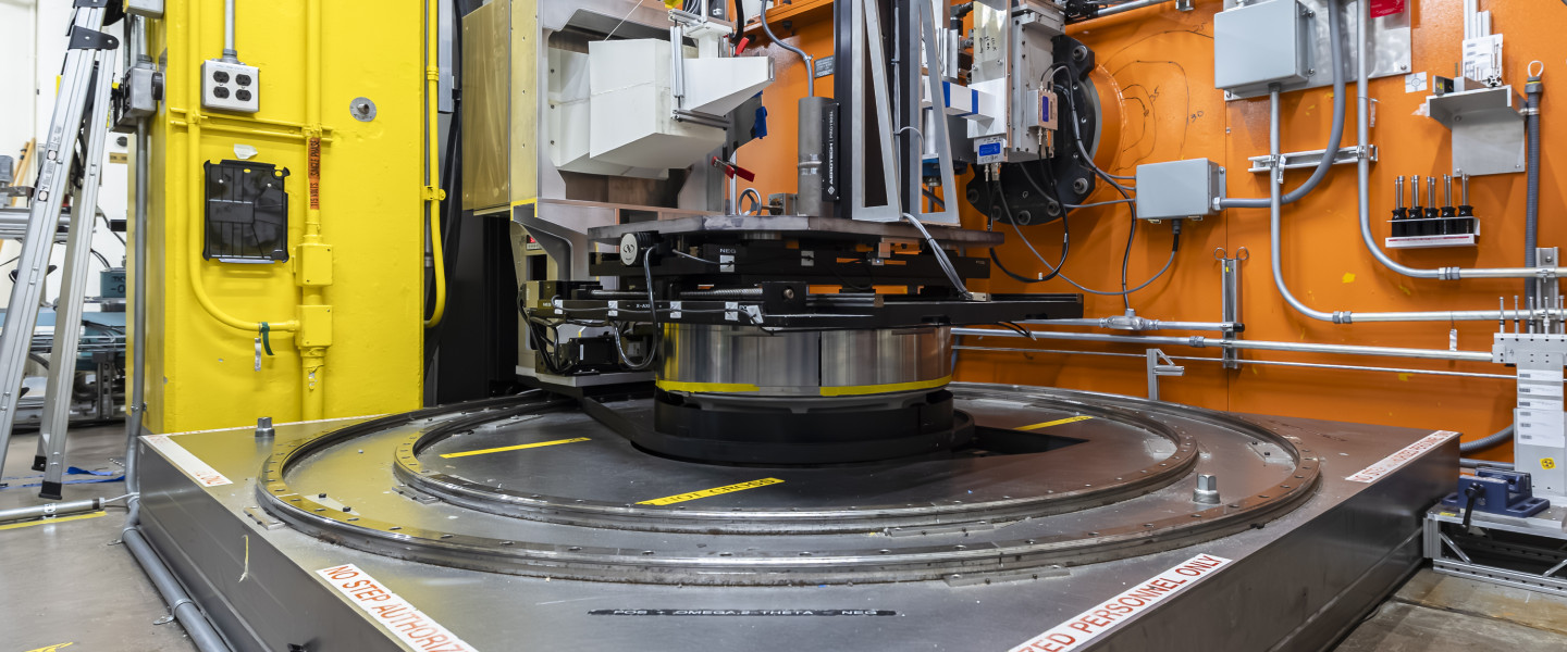
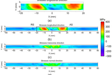
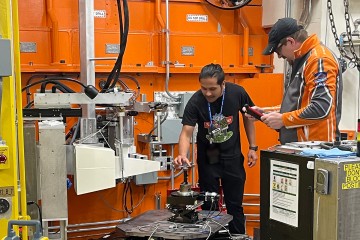
Scientists and engineers use the HB-2B High Intensity Diffractometer for Residual stress Analysis (HIDRA) to study residual stresses in steel, aluminum, superalloys like Inconel, and other such structural materials. Elastic strain in these materials can be determined by measuring their interplanar atomic spacing, and this instrument is designed to use the high- penetration power of neutrons to generate “maps” of the strain resulting from residual or applied stresses in bulk materials. A detailed understanding of residual stresses is critical for the safe and effective functioning of virtually every type of structural engineering material.
The HB-2B HIDRA beam line is optimized for strain measurement and determination of residual stress in engineering materials. The incident beam is delivered at a fixed angle of 88° by a double-focusing Popovici-Stoica silicon monochromator (replacement unit installed Fall 2025, HFIR Cycle 513). Both vertical and horizontal focusing are used. The wavelength is chosen from a variety of monochromator crystal settings with a selection of wavelengths from 1.45 to 2.67 Å.
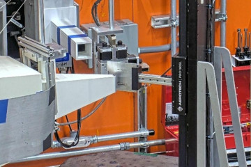
The sample goniometer is designed for spatial scanning of residual stresses at depths from a millimeter to several centimeters in most metals—for example, ~3–4 cm in steel and greater than 10 cm in aluminum. Spatial resolution at a fraction of a millimeter is possible depending on the material. The scattering from the test sample is recorded with a 30 cm × 30 cm 2D position-sensitive detector (DENEX 300TN) located approximately 1 meter from the sample. The nominal scattering angle (at the center of the detector) can be set from 65° to 120° but is normally near 90°. The detector spans approximately 17° in 2θ.
In situ loading experiments are supported at HIDRA using a Psylotech load frame shared across multiple HFIR/SNS beamlines. Contact instrument staff for availability and compatible specimen geometries.
HIDRA offers an integrated suite of web-based experiment planning tools and open-source analysis software that together support every stage of a residual stress measurement campaign -- from pre-proposal feasibility assessment through final stress/strain calculation.
HIDRA Planning Suite (NOVA / NDIP)
Before writing a proposal or scheduling beam time, users can assess experiment feasibility and estimate required measurement time using the HIDRA Planning Suite, hosted on ORNL's Neutron Data Interpretation Platform (NDIP). The tools run entirely in a web browser -- no software installation is required -- and are accessible to all registered ORNL users via XCAMS/UCAMS credentials.
The Planning Suite includes two integrated tools:
Count Time Estimator -- answers the fundamental planning question: how long must I count per measurement point for my material, gauge volume, and sample depth? The tool uses a calibrated peak-height scaling law combined with Lambert-Beer neutron attenuation to compute required exposure times. Users select from a built-in material library (ferritic steel, austenitic steel, aluminum, nickel, Inconel 718, copper) or enter a custom alloy composition and density. The recommended monochromator setting for each material is highlighted automatically. Results include interactive count-time contour maps and attenuation curves that can be exported as high-resolution figures for inclusion in proposals.
Mapping Planner -- simulates a complete residual stress mapping scan on a user-defined sample geometry. For every planned measurement point the tool computes incident and diffracted beam path lengths through the material, applies the attenuation correction, and classifies each gauge volume location as Fully Buried, Partially Buried, or Outside the sample. Results are displayed in an interactive 3D visualization with beam-path overlays, and a downloadable CSV table reports per-point burial status, path lengths, and required count times. Sample geometry can be entered as a simple cuboid or uploaded as a custom STL file for complex shapes such as welds, pressure vessels, or turbine blades.
The Count Time Estimator and Mapping Planner are linked: once count-time parameters are set in the Estimator, a single click transfers them to the Mapping Planner, ensuring consistent physics across both tools.
Access the HIDRA Planning Suite through the Engineering Diffraction category on the NOVA dashboard at ndip.ornl.gov/nova.
| Beam Spectrum | Thermal |
| Selectable Wavelength (Monochromator setting) |
88°, λ = 1.452 Å (Si 511); 1.452 Å (Si 333); 1.540 Å (Si 422); 1.731 Å (Si 331); 1.886 Å (Si 400); 2.275 Å (Si 311); 2.667 Å (Si 220) |
| Flux on sample | 3 x 10⁷ n/cm2/s (Si 331 and Si 400) |
| Detector angle range | 65–120° (via detector arm rotation); optimal near 90° |
| Detection system | 30x30 cm 2D Denex |
| 2D Detector Coverage | 17° 2θ |
| Z elevator Z translation |
Z ± 250 mm |
| Nominal Gauge volume |
Slits: |
| Peak location precision | 0.0003° 2Θ (~100–150 microstrain) |
| Sample environments | Huber Eulerian cradle and/or phi-chi stage for tensor and texture Vacuum and environmental furnaces CrESL creep electrostatic levitator Integration with flexible specialized sample environments |
| Max. Sample Size | Weight Limit: up to 2,400 kg (configuration dependent; contact instrument staff for large or unusual samples) Dimensions: consult with team |
New in 2025: A replacement Popovici-Stoica monochromator was installed in HFIR Cycle 513 (Fall 2025), delivering increased performance across all wavelengths.
Lead Instrument Scientist
Instrument Scientist






Oak Ridge National Laboratory is managed by UT-Battelle LLC for the US Department of Energy
